The objective of this tutorial is to describe step by step how to make the hydraulic part of a sprinkler system.
Use this tutorial as the guideline in order to design yours, all components (brand, size, quantity, capacity…) described below is my own design as example but each projects are differents. At the end of this tutorial, you will be able to use the sprinkler manually.
Useful conversion Inch/Metric: 1⁄2” = 15/21 3⁄4” = 20/27 1” = 26/34 1⁄4” = 33/42
Water inflow level
Define system capacity
The Hunter tutorial below helped me: Hunter tutorial
Check pressure level
Check pressure level with a manometer in order to fix the pipe size and number of rotors by zones.
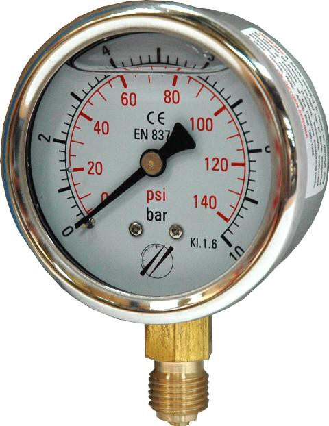
Here my results as example:
- Static pressure: 3.5 Bars 50 PSI
- Water meter: 1”
- Service line: 1”
- Design capacity: 53 l/min 14GPM -> 3,18 m3/h
- Working pressure: 2 Bars 29 PSI
According to the rotor Rainbird 3500 specification:
- Nozzle standard 2; 8.2m radius; 0.47m3/h
So according to my design capacity 3.18 m3/h => 3.18/0.47 = 6.76 so I can use 6 rotors maximum by zone.
Note: The pressure decrease of 0.25 Bar every 10m for a 25mm pipe. So you have to get it in consideration to calculate the capacity for distanly zones from your manometer.
My biggest zone is a square of 76 m2 = with 4 rotors with 8.2m radius, I will cover the zone with at least pressure.
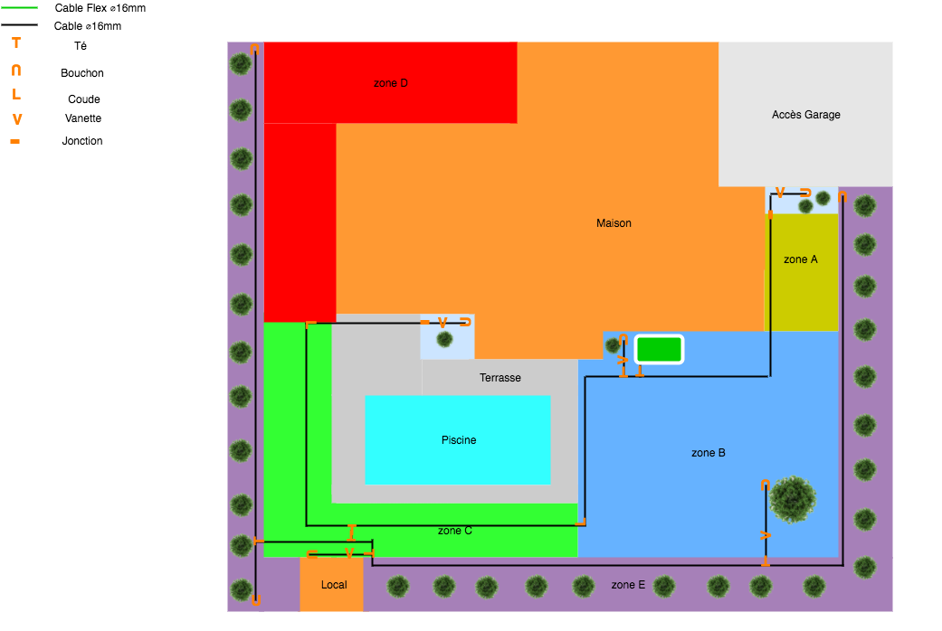
Zones definition
Split your land in the largest square and rectangle as possible. But drop by drop irrigation and lawn irrigation must be separate.
Note: According to your rotors selection, you need to choose rotors able to cover these zones. Example for my surface, I opt to Rainbird 3500 which cover all my requirements. See more here.
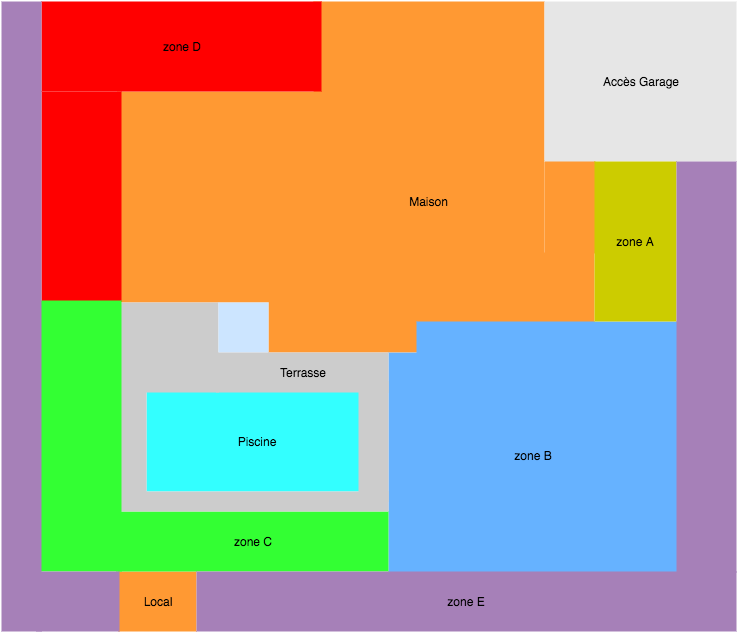
| Zone | Description | Diameter (mm) | Surface | Rotors |
|---|---|---|---|---|
| A | Lawn irrigation | 25 | 21.5m2 | 2 |
| B | Lawn irrigation | 25 | 76m2 | 4 |
| C | Lawn irrigation | 25 | 45m2 | 4 |
| D | Lawn irrigation | 25 | 45m2 | 3 |
| E | Drop by drop irrigation | 16 | - | - |
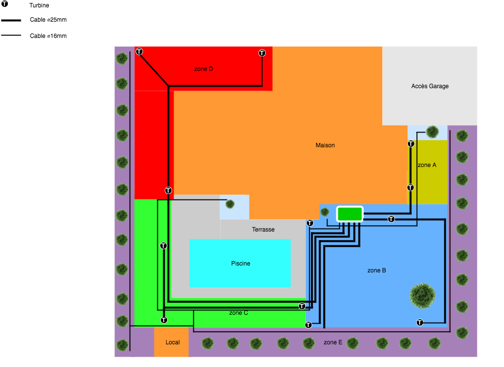
Network definition
1) Locate your water main supply
First check your main supply pressure. For my part, I had 8 Bars ! Yes My water tower is 50m above my house (1 Bar every 10m and the water tower 30m height). So I set up a pressure reductor in order to limitate the pressure to 3.5Bars. It’s a good option in order to not damage your house equipments (plumbing, washing machine… and your future sprinkler system).
2) Define valve boxes location
This location must be strategic to optimize pipe length and pressure loss.
3) Place rotors for each zones
Rotors must be place at first in the corner of each zone. See below the best practices to place rotors.
- Place main network (25mm pipe) as closely as possible to rotors;
Note: You can follow your house wall in order to facilitate the maintenance.
- Place secondary network (16mm pipe) to join main network and rotors;
Note: You could adjust easily the secondary network with flexible pipe (16mm)
- Place drop by drop network (16mm pipe)
Note: Drop by drop must pass through all plants. It will be easy to divide in sub-network with mini gates
Installation
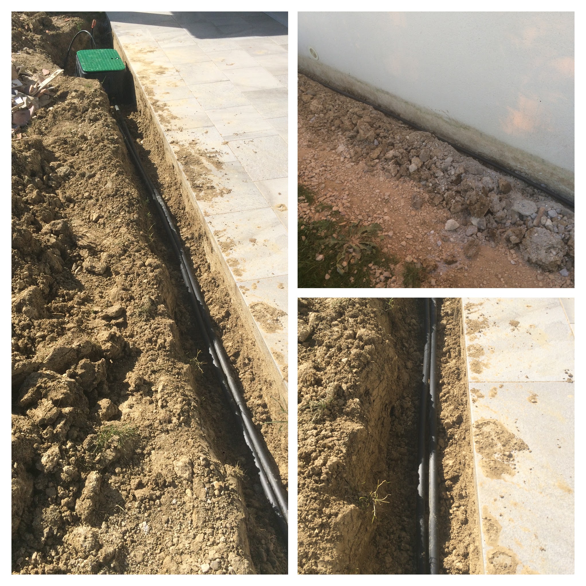
Dig trenches and set main pipe
- Dig trenches: 25cm depth and 20cm wide;
- Roll out and cut the pipe. Leave a margin in order to join easily connectors.
Components:
| Component | Description |
|---|---|
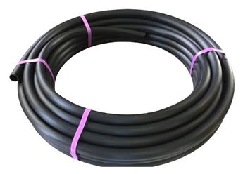 |
Polyethylene pipe 25mm 25m HD 6Bars |
Tools: Pickaxe, Spade, Stanley knife, Tape and Guiding line.
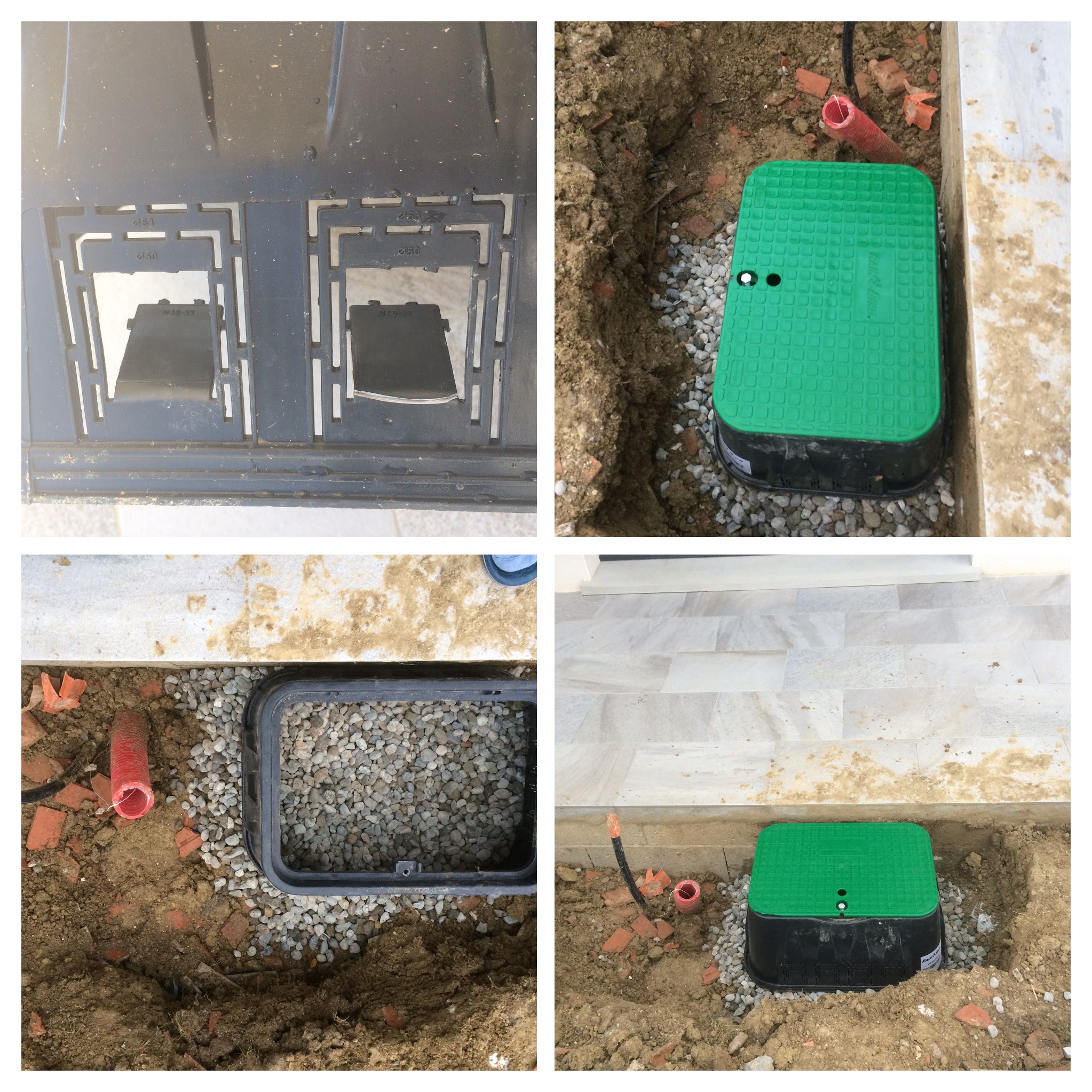
Valve boxes
- Valve boxes must locate near the water main and electrical supply;
- Choice the right size according to the number of valves that you need;
- Dig a large hole in order to easily working;
- Create a bed of pebbles for stability and avoiding mud after water leak;
- Cut out the plastic entrance for each valves.
Components:
| Component | Description | Unit price |
|---|---|---|
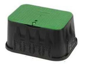 |
Valve boxes Rain Bird 62x46x30,5cm | 38.81 |
Tools: Pickaxe, Spade, Stanley knife, Tape.
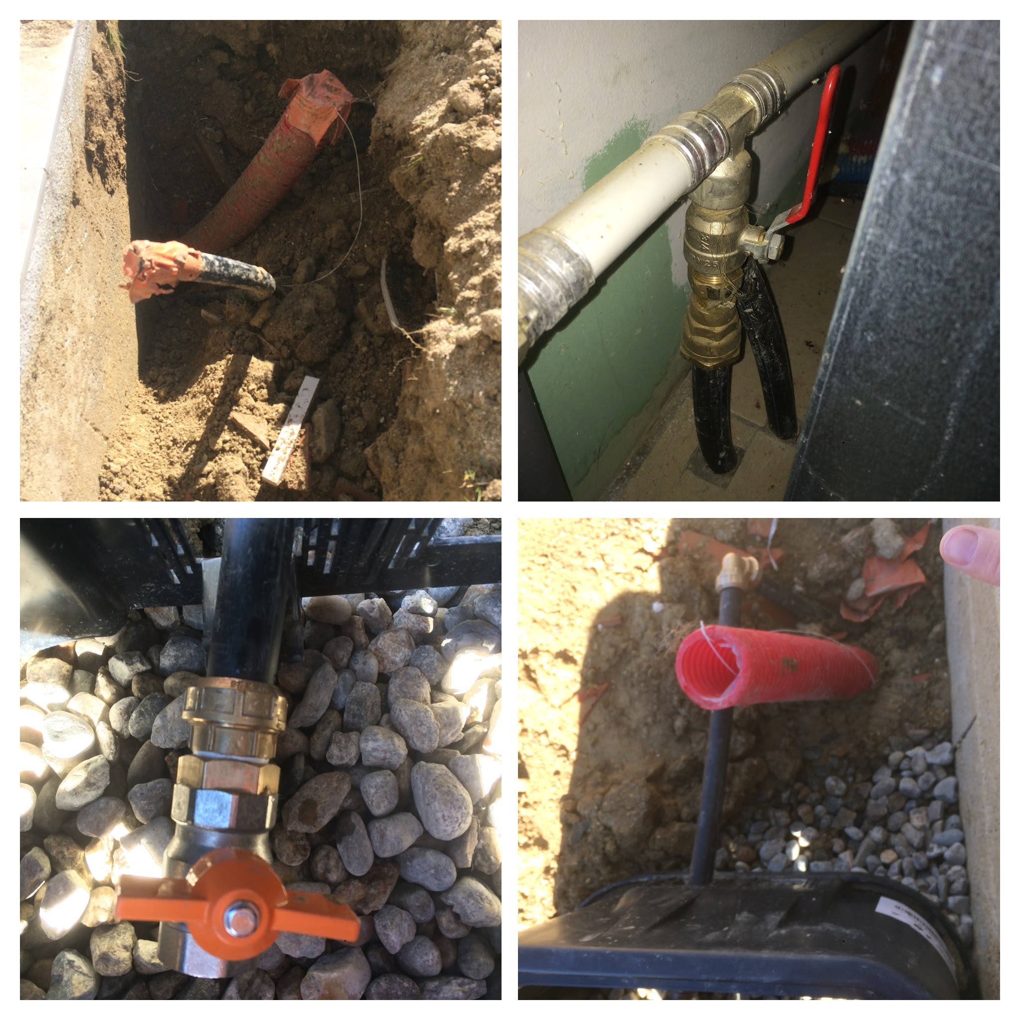
Water main supply
Now the valves box installed, we can connect to the water supply. In my case, I had planned a 25mm pipe under my house to join directly my garden. So I just added a brass union to join the water supply with my 1/4 turn gate.
Tools: Wrench, teflon tape, stanley knife
Note: I also another 1/4 turn gate in my garage in order to turn off easily in each side. Useful to avoid water pipe freezes.
| Zone | Description | Quantity | Unit price | Total |
|---|---|---|---|---|
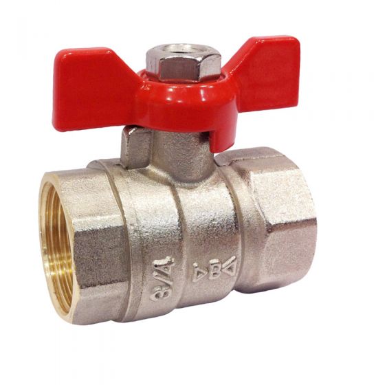 |
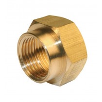
Gate FF 26x34 | 1 | 10.75 | 10.75 |
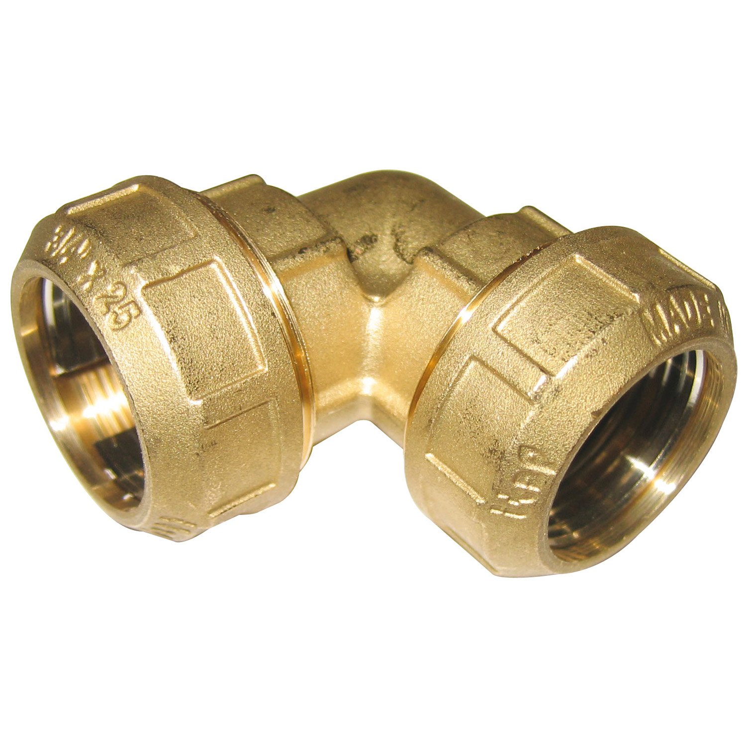 |
Brass elbow 19x25 | 1 | 7.5 | 7.5 |
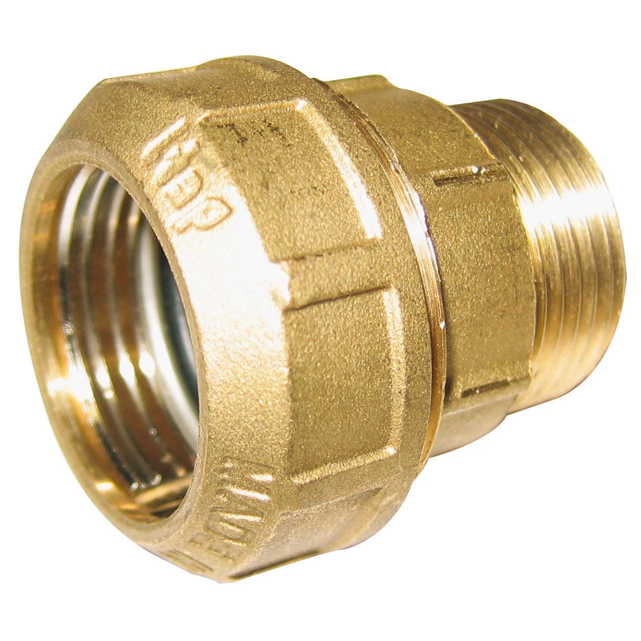 |
Brass adapter male 19x25 | 1 | 4.25 | 4.25 |
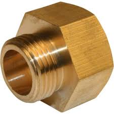 |
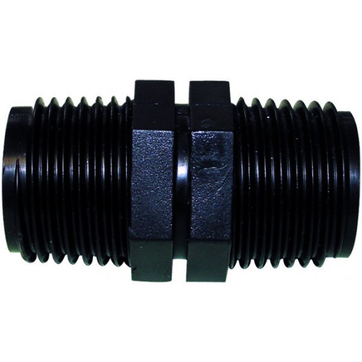
Brass nipple Female 20/27 -> Male 26/34 | 1 | 4.08 | 4.08 |
|
Water Pressure Gauge INOX radial 0 à 6 bars x1 | 1 | 9.65 | 9.65 |
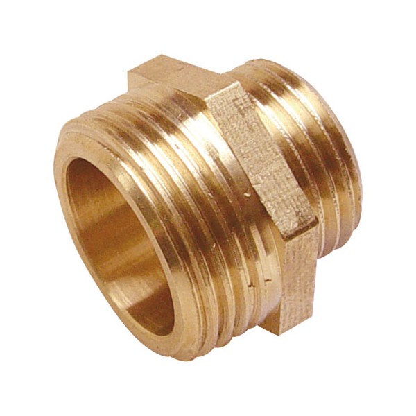 |
Brass adapter 26/34 Male -> 20/27 Male | 2 | 4.2 | 8.4 |
 |
Brass adapter 20/27 Male -> 12/17 Male | 1 | 2.375 | 5.75 |
 |
Brass nipple 8/13 Female-> 12/17 Male | 2 | 1.425 | 2.85 |
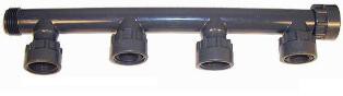 |
Clarinet 1” | 1 | 16.06 | 16.06 |
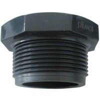 |
End plug PVC male 1” | 2 | 1.55 | 3.10 |
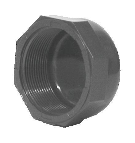 |
End plug PVC female 1” | 2 | 1.95 | 3.9 |
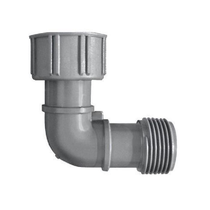 |
Elbow collector MF 1” | 1 | 5.05 | 5.05 |
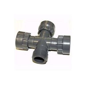 |
Cross collector 1” | 1 | 8.95 | 8.95 |
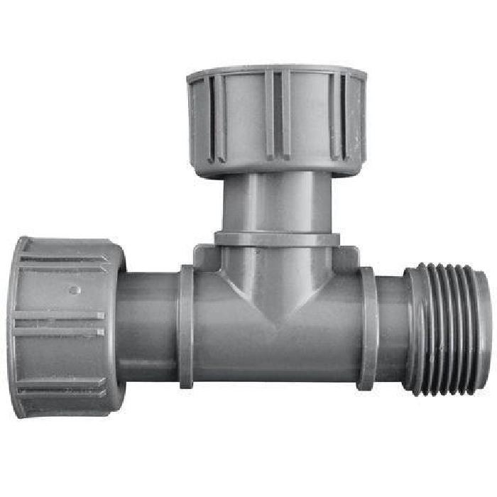 |
Tee collector 26x34 MF 1” | 1 | 4.2 | 4.2 |
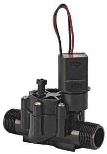 |
Irrigation valve RAIN BIRD DV 1” MM NR 24V | 4 | 14.94 | 59.76 |
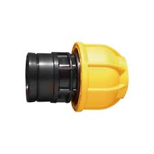 |
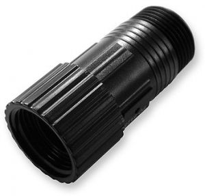
Adapter compression 25mm | 4 | 2.5 | 10.0 |
| - | - | - | - | 164.25 |
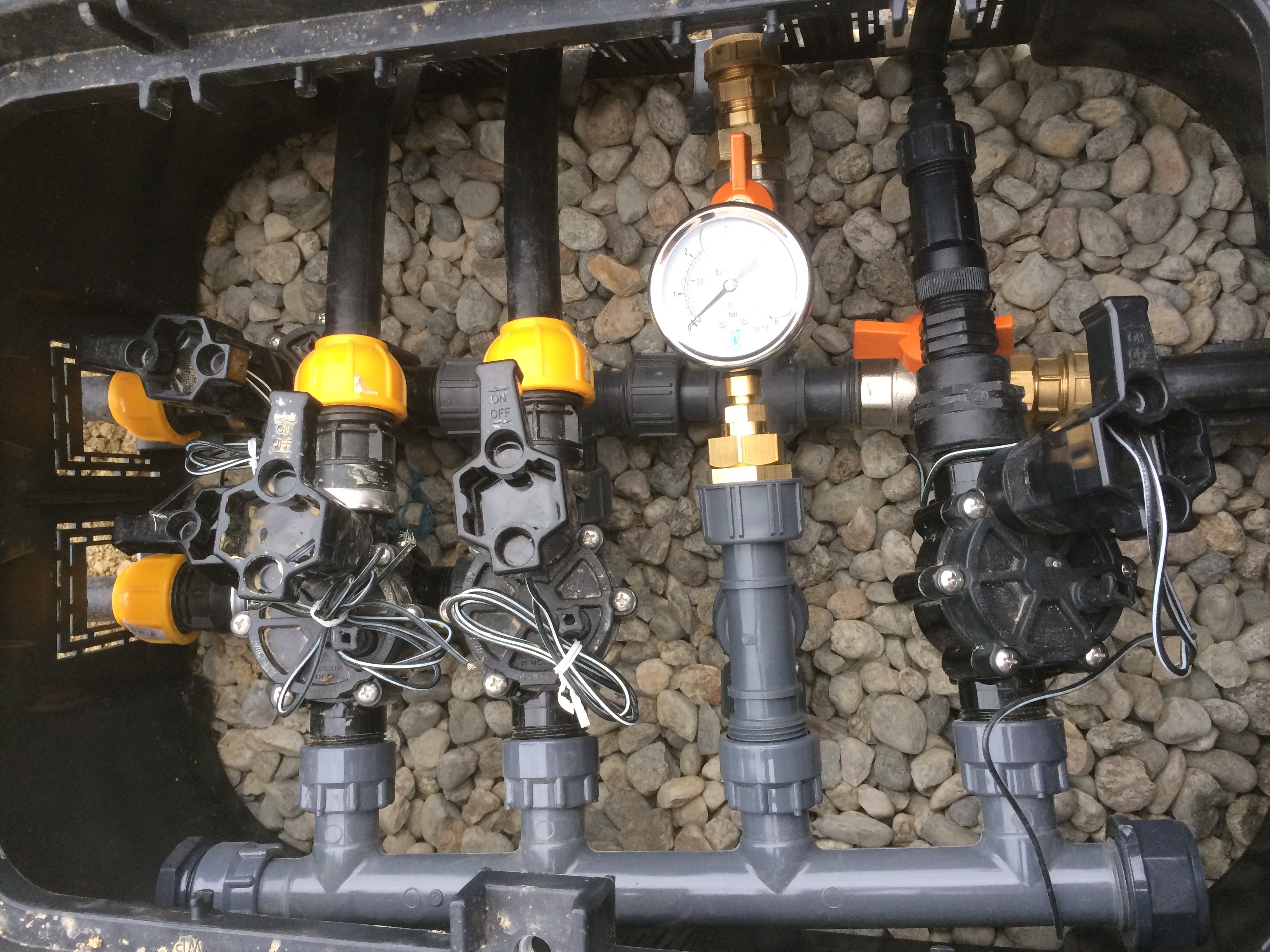
Valves
Each project will be different according to your number of valves, the location, the valves box… So you need to pay attention to design your installation. In my case, I designed with 2 floors in order to install: 5 valves, 2 gates and 1 manometers.
- Put teflon on each threading which don’t contain any seal.
- Every valves are compression connector to join the main network (25mm).
- A pressure reducing is used for drop by drop network (16mm).
- I added another 1/4 gate for supplying my solar shower.
- I added a manometer to control the network pressure.
- Don’t forget to keep few space for the electrical part.
Connections
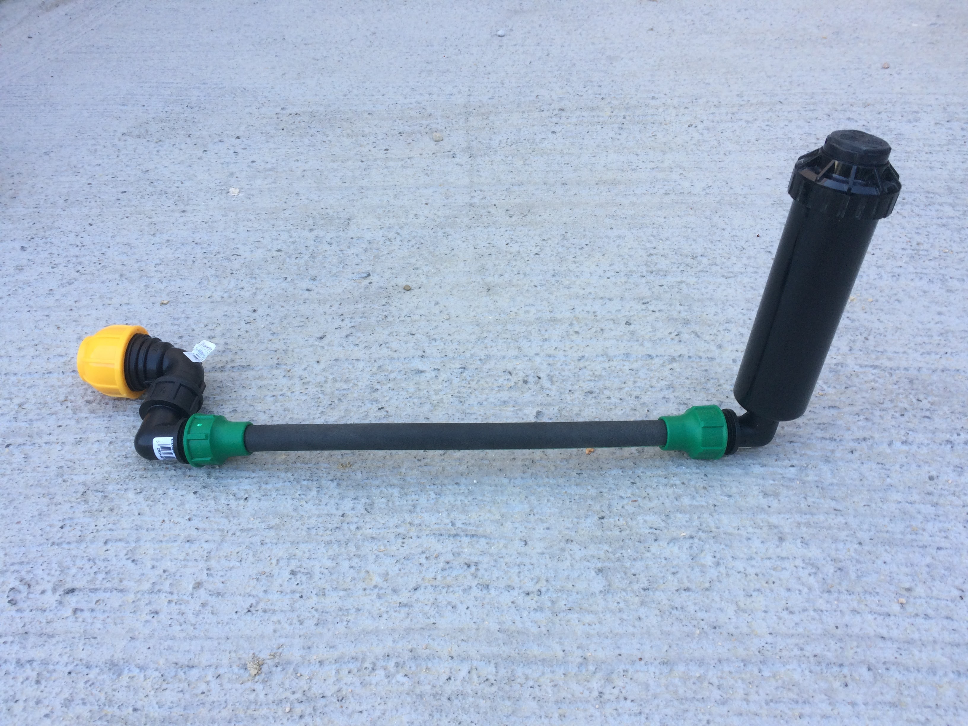
Wire pipes, elbows, tees et rotors
| Component | Description | Quantity | Unit price | Total |
|---|---|---|---|---|
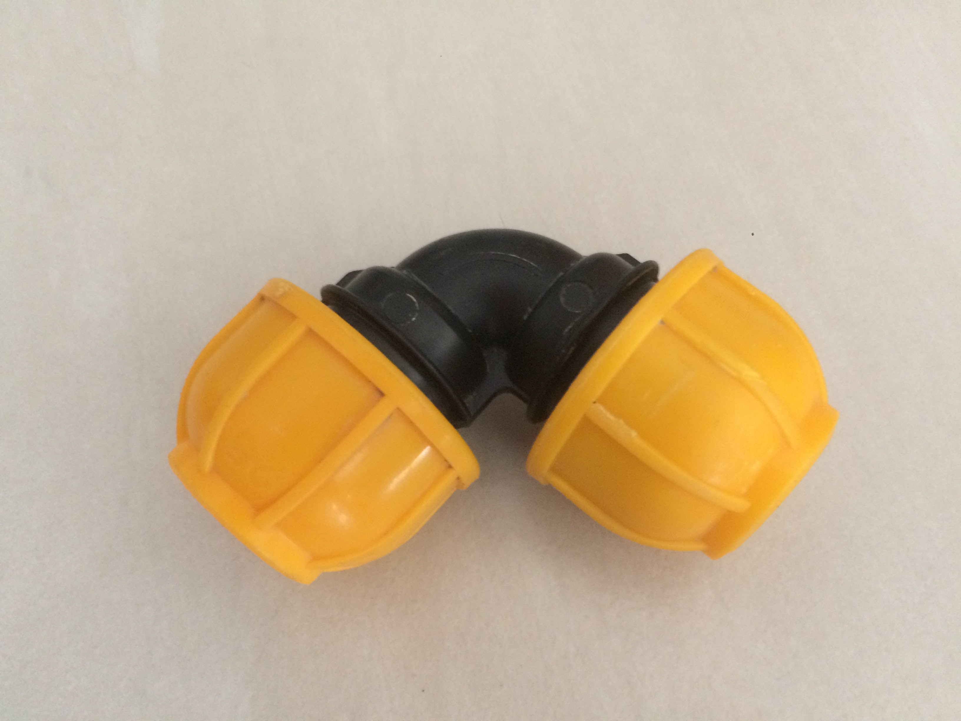 |
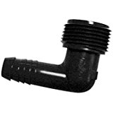
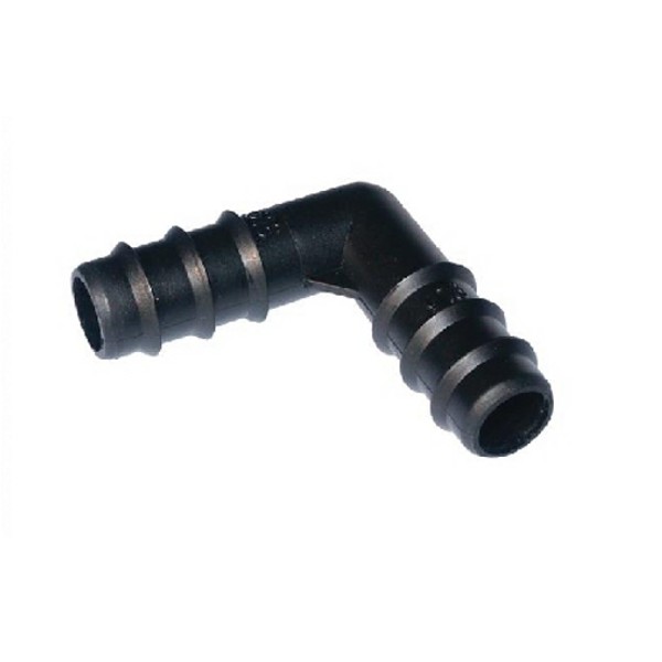
Compression elbow connector | 14 | 3.05 | 42.7 |
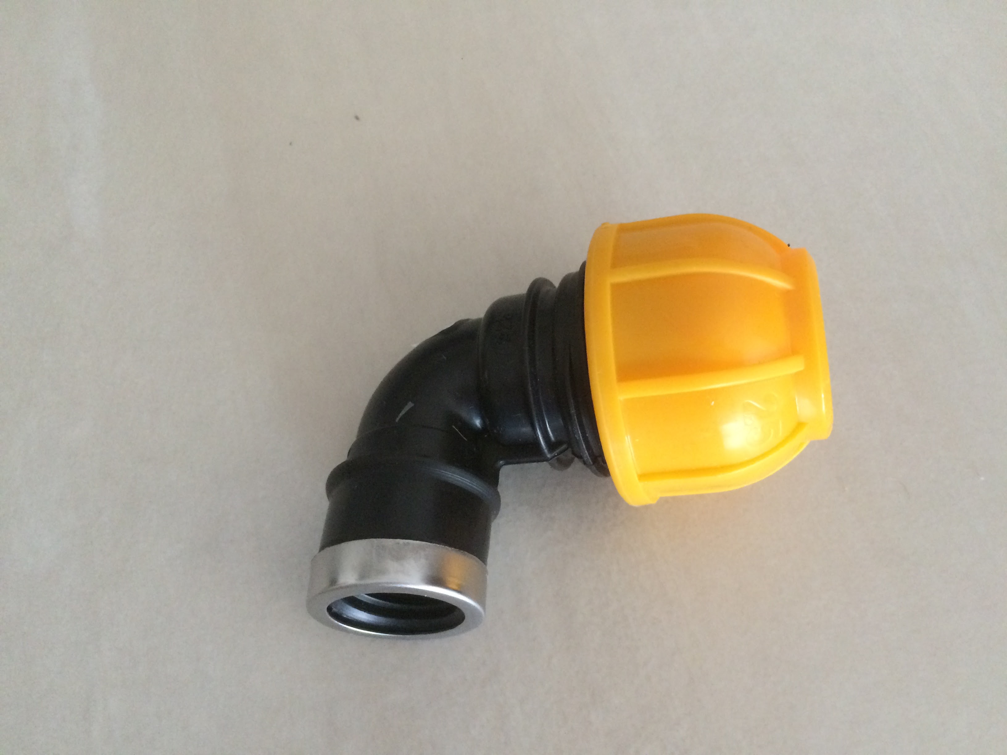 |
Fitting compression elbow connector | 4 | 3.05 | 12.20 |
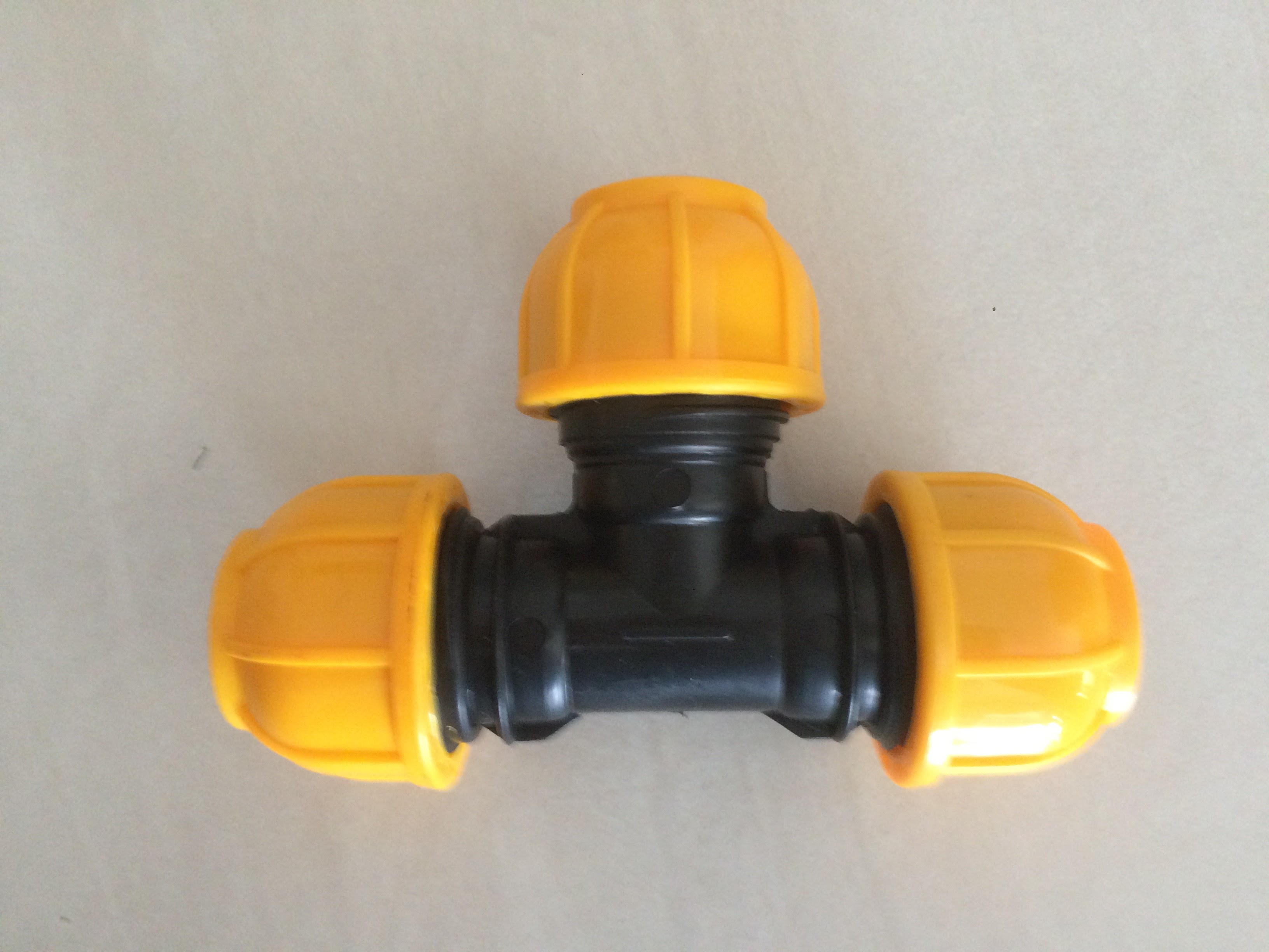 |
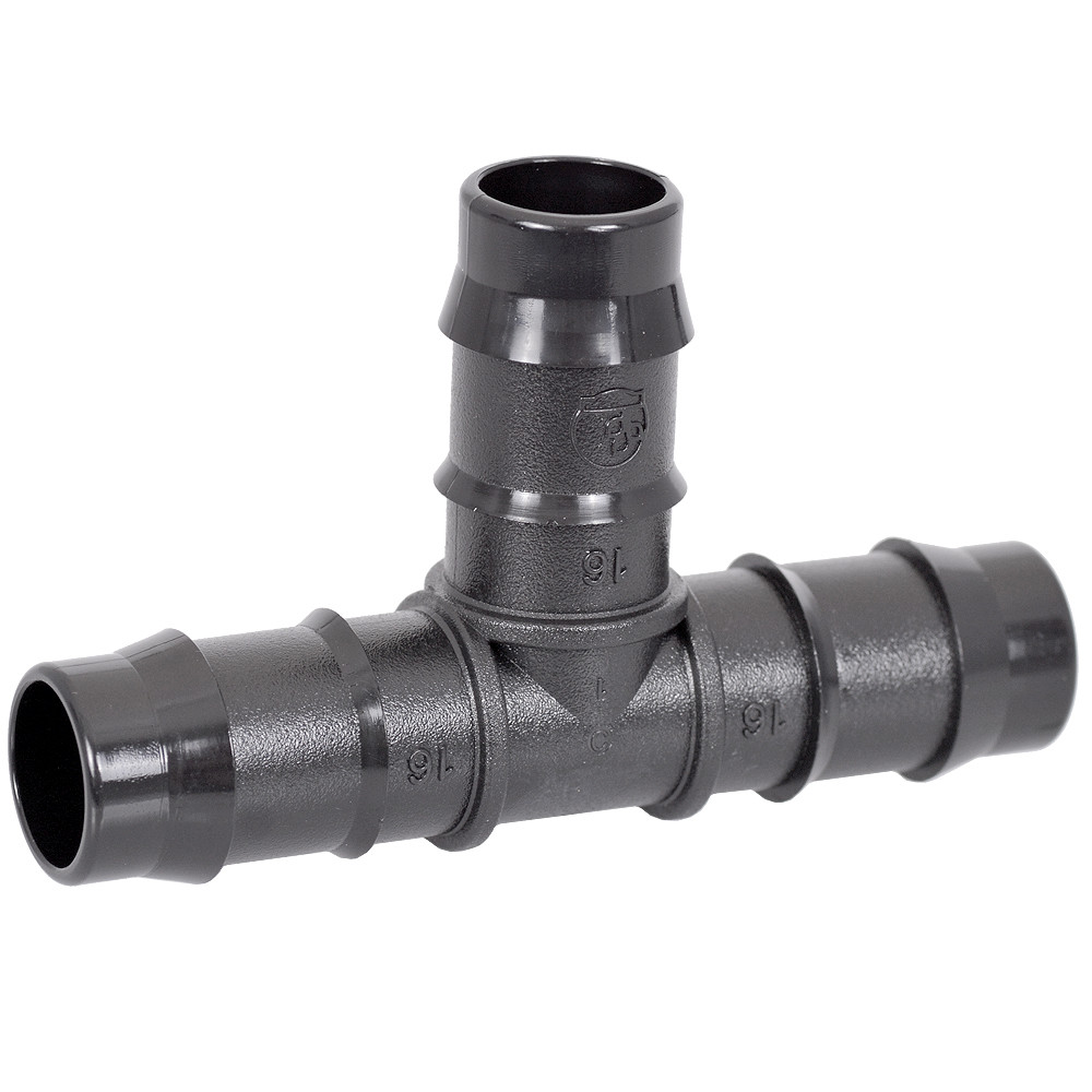
Compression tee | 4 | 4.05 | 16.2 |
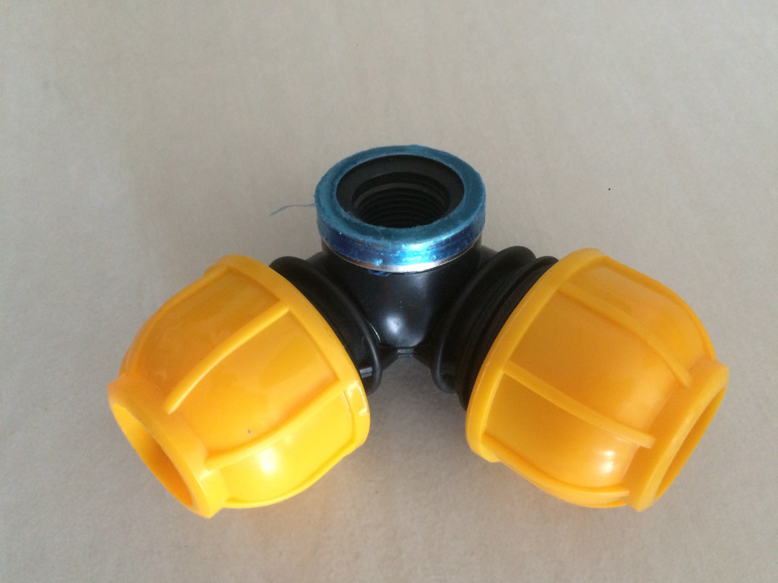 |
Compression fitting female tee | 9 | 4.65 | 41.85 |
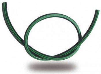 |
swing pipe 30m SPX-FLEX 30m | 2 | 27.0 | 54.0 |
|
polyethylene irrigation pipe 25mm 50m HD 6Bars | 3 | 30.9 | 92.7 |
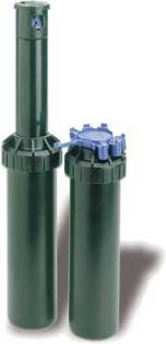 |
Rotor RAIN BIRD 3504 PC (1/2” F) | 13 | 6.97 | 90.61 |
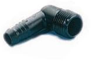 |
Swing Pipe - 1/2” MNPT Elbow | 13 | 0.24 | 3.12 |
 |
Swing Pipe - 3/4” MNPT Elbow | 13 | 0.24 | 3.12 |
| - | - | - | - | 356.3 |
Drop By Drop
Advices:
- Regarding the drop by drop, we have to add a pressure reductor 1.2bars 17PSI (1 14.5 PSI à 1.5bars 21.75PSI)
- Add mini threading valve in order to control different zones (see components below).
- I set 1 dripper by bush, 3 drippers by palm tree, 2 drippers by conifer, 2 drippers by olive tree
Components:
| Component | Description | Quantity | Unit price | Total |
|---|---|---|---|---|
|
Irrigation valve RAIN BIRD DV 1” MM NR 24V | 1 | 14.94 | 14.94 |
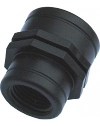 |
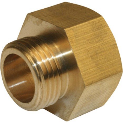
Reducing Coupling Female Thread female/female 1” -> 3/4” | 1 | 2.05 | 2.05 |
 |
Nipple PVC male/male 3/4” | 1 | 1.09 | 1.09 |
 |
Pressure Regulator 3/4” Hose Thread 25PSI female/male 3/4” | 1 | 5.99 | 5.99 |
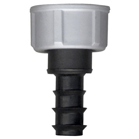 |
Thread adaptator male 3/4” -> 16mm | 1 | 0.42 | 0.42 |
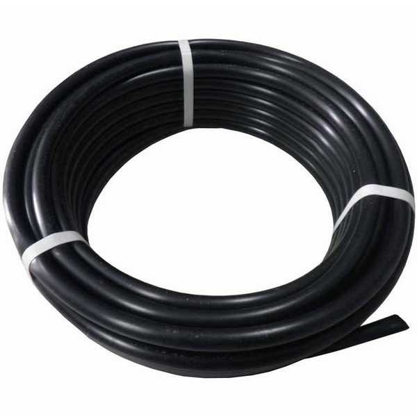 |
polyethylene irrigation pipe 16mm 25m | 5 | 6.90 | 34.5 |
 |
Elbow 16mm | 6 | 0.25 | 1.50 |
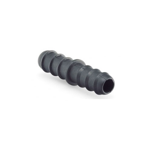 |
Adapter 16mm | 6 | 0.25 | 1.50 |
 |
Tee 16mm | 4 | 0.54 | 2.16 |
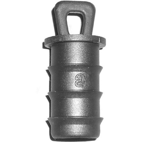 |
End plug connector 16mm | 8 | 1.65 | 13.2 |
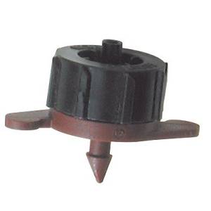 |
Dripper | 100 | 0.23 | 23.0 |
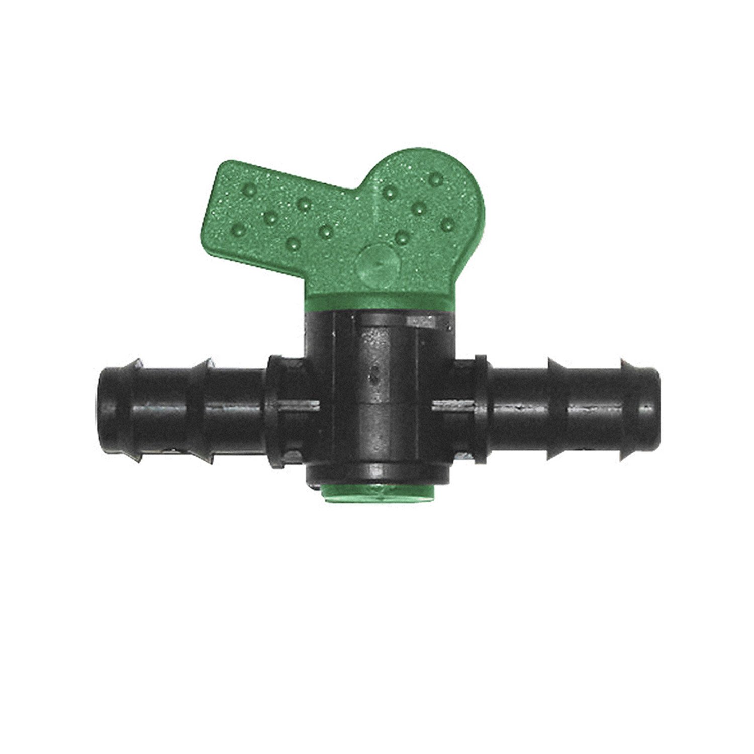 |
Mini Threading valve 1/4 de turn male/male 16mm | 6 | 2.45 | 14.7 |
| - | - | - | - | 115.05 |
Tools:
| Component | Description | Price |
|---|---|---|
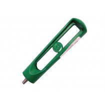 |
Irrigation hole punch | 3.40 |
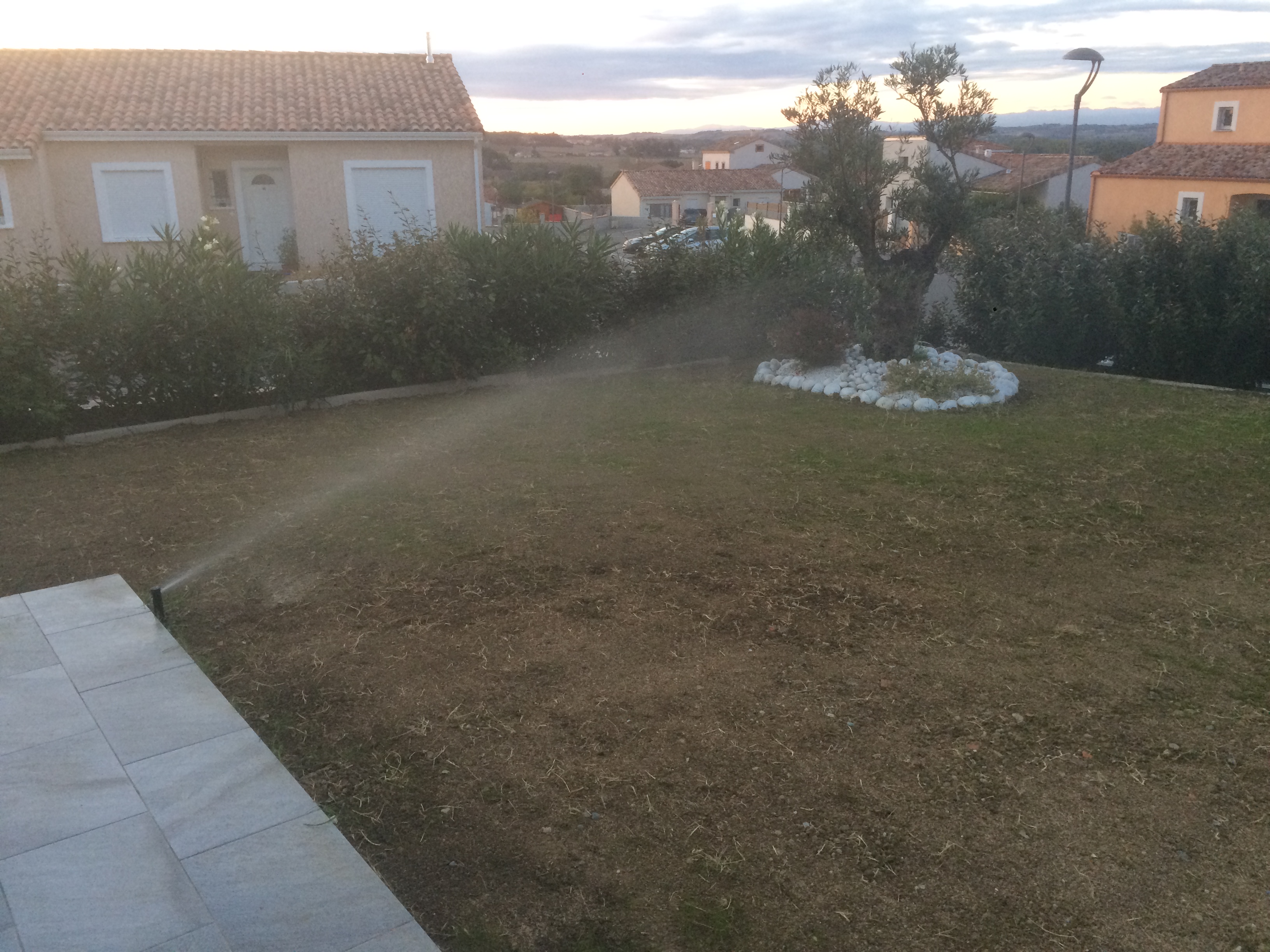
Result test
- Open the main gate.
- Check the pressure and joins are well set
- Open gate manually with 1/4 turn.
- With a screwdriver adjust your rotor covering.
- Total cost for my project: 677.81€
Tools: screwdriver.
We can now use the sprinkler manually from the valve box. The next tutorial will describe electrical and electronic part to automatize the system.